What is the pressure in the interior of the Earth?
Vince Gutschick, NMSU (emeritus)/ Global Change Consulting Consortium / Las Cruces Academy
12 May 13
I was reading a recent issue of Science (26 April 2013) that explored the quandary of the equation of state of iron at the high pressures at the boundary of the inner core. There, it was stated that the pressure was 330 GPa (gigapascals; one atmosphere is 100 kPa or 0.0001 GPa; there is a short note at the end of this exposition about pascals as a unit of measurement, and about Blaise Pascal). That is, the pressure at the center is 3.3 million atmospheres! Could I derive this from a knowledge of the density and radius of the Earth and the hydrostatic principle – that the pressure gradient, acting upward (dP/dr <0, measuring radial distance, r, from the center) serves to counter the gravitational force that tends to pull any “rock” layer inward? The justification for treating “solid” rock as a fluid, is that rock does act like a fluid – albeit a very viscous fluid – on long time scales. That is an experimental fact as well as being in evidence in mountain folding and the now-familiar tectonic movements of the whole Earth’s crust.
This exercise uses basic differential and integral calculus and simple physical principles. It also leads to a view of how physics can be done to understand what happens in places that are impossible to access directly.
Hydrostatic principle:
Consider a thin shell or layer of rock extending radially from r to r+dr. It has a mass equal to its volume (area, 4πr2, multiplied by the depth dr) multiplied by its density, ρ(r). The gravitational force on it equals its mass multiplied by the local gravitational acceleration, g(r). The pressure gradient pushing outward exerts a force (with a negative sign, acting in the direction opposite to the radius vector r) equal to the area of the shell multiplied by dP/dr. Thus,
![]()
I’ll use two approximations, one rough and one quite precise, for the local density of rock, assumed to be isotropic laterally (not varying with angular direction at any depth).
We need a way to compute the local gravitational acceleration, g(r), at any depth. A wonderful theorem from mathematical physics says that g(r) is simply proportional to the total mass in a sphere, not affected by the distribution of mass with depth. The sphere’s distribution of mass with angle has to be uniform. This theorem only holds for a force that has a dependence on distance of 1/r2, as gravity does. For any mass, m, located above a spherical mass, M, the force is
![]()
Here, G is the universal gravitational constant, 6.671×10⁻¹¹ m3 s-2 kg-1. We can compute the mass M, contained within a sphere of radius r from the center of the Earth by integrating over density. In any shell between r and r+dr, the mass is as calculated earlier, dm = (area)(thickness)(density) = 4πr2 dr ρ(r). We can integrate this from 0 to r, to get

First approximation calculation of mass and pressure:
Let me introduce the first approximation, that the density is uniform over depth and equal to the average density of the Earth, (which is about 5.5 g cm-3, or, to use real SI units, 5.5×10³ kg m-3). Then,

(The vertical bar is the best I could get in MathType’s free version to indicate the evaluation of the expression at the two limits, r as the upper limit and 0 as the lower limit).
Then,
![]()
We could use this, carrying the involvement of G and , or we can make it simpler. Clearly, the gravitational acceleration at the surface of the Earth, which we can call g0, is just the expression above evaluated at r = R, with R as the radius of the Earth, about 6400 km = 6.4×10⁶ m. We see that
![]()
That is, the local acceleration is just the surface acceleration multiplied by the fractional distance out from the center.
We can now integrate for P(r). Let’s express this as the increment from the surface value, P = 0 (neglecting the small atmospheric pressure):
![]()
We integrate to get

We can evaluate this at any depth. In particular, at the center of the Earth, r = 0, we have
![]()
We can evaluate this:
![]()
This is about half the correct answer! Why so? It’s because the mass of the Earth is distributed unevenly, with much-increasing density with increasing depth. We have to use a better description of ρ(r).
Quite accurate approximation, using the detected variation of density with depth:
Density vs. depth is detected by recording transit times for seismic (earthquake) waves across the depths of the Earth. One has to know about the refraction of waves as they traverse different densities at oblique angles.
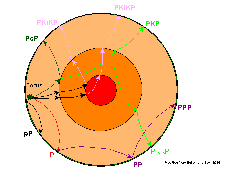
http://faculty.weber.edu/bdattilo/shknbk/notes/insdearth.htm
The travel time across the interior paths depends on the length of the path and on the details of the speed of sound in each layer. The speed of sound depends on the density of the material and the elastic constants or springiness. The latter involves the equation of state of the material, which requires laboratory measurements of materials apparently present at various depths, with the measurements made over ranges of pressure and temperature. Determining density and mineral composition vs. depth is then an iterative process, which I won’t go into at this point, though there are notes at the end of this exposition.
A simple summary of the measurements is given here:

In any event, the best estimates for the detailed density of material in the Earth vs. depth are illustrated below:
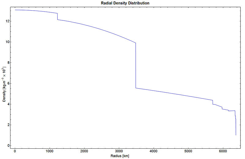
 https://en.wikipedia.org/wiki/File:RadialDensityPREM.jpg
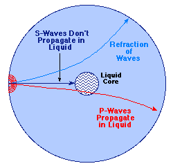
Side note: how do we know that the Earth’s inner core is liquid? It’s because there are two kinds of earthquake waves, once with compressions and rarefactions along the direction of the wave travel (P-waves) and the others with the compressions and rarefactions perpendicular to the direction of travel (shear or S-waves). Shear waves can’t travel through the liquid core. The paths that intersect the liquid core become obvious because only P-waves are found at other places on the surface where our detectors are.
http://csep10.phys.utk.edu/astr161/lect/earth/interior.html
To continue: we want to integrate ρ(r)g(r). To do this analytically (with algebraic formulas), I need to make simple formulas that approximate ρ(r). Here are the approximate formulas:
For r [0, 1400 km), ![]()
The second, negative term accounts for the density (as specific gravity) dropping from 13.1 to 12.8 over the 1400 km (really, it drops to 12.7, but the curve is convex, lying above the straight line in the middle, so that the modified formula captures the average well).
For r [1400 km, 3500 km), ![]()
The real range is from about 12.1 to 10.1, but, again, the curve is convex, so I adjusted the endpoints to 12.2 and 10.2 to get the average correct.
For r [3500 km, 5700 km), ![]()
The range is specific gravity is from 5.6 down to about 4.4, and it’s pretty linear.
For r [5700 km, 6317 km], ![]()
The specific gravity is rather ragged over this range, but within an “average” (root-mean-square) error of about 0.1 in these units, the trend looks close to a linear variation from about 4.1 down to 3.1.
Let’s use some symbols to cover the various ranges. We’ll say that
![]()
Here, R0i is the upper limit of the layer or segment – that is, it is 1400 km for segment 1 (inner core) that runs from 0 to 1400 km, it is 3500 km for segment 2 (outer core) that runs from 1400 km to 3500 km…and, similarly, 5700 km and 6317 km for segments 3 (inner mantle) and 4 (outer mantle). I set it to 0 for i-1 = 0.
Now let’s use the algebraic formulas to get g(r) within each segment. This means, first, getting M(r), the mass within the limits 0 to r.
Segment 1 (inner core):
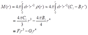
The numerical values of Fi and Gi are readily calculated. Then, we have
![]()
The integration of –ρ(r)g(r) then takes the form
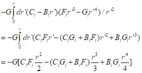
(Sorry for the confusion offered by having G = gravitational constant and Gi for algebraic equation coefficients.)
We can evaluate this formula at any radius, r, in the inner core (segment 1).
Segments 2, 3, and 4:
The integrand is not continuous across the boundaries (density changes discontinuously), so, in integrating for the mass, M(r), we simply add the result of the integration from all lower segments:
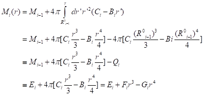
Here, Mi is the total mass in all the segments from 1 to i – that is, M1 is the mass in the inner core (segment 1), M2 is the mass in the inner core plus the outer core, etc. The definitions of Ei, Fi, and Gi should be easy to see by inspection.
We can plug this form into the integral of dP/dr to get the decrement in pressure from the lower boundary of the segment, R0i-1, to the current radius, r, as
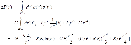
The term in brackets is to be evaluated at the upper limit, r, and then its value at the lower limit, R0i-1, is to be subtracted, as is standard in integration. The expression looks like that for segment 1, with the addition of the first two terms in brackets, which do not occur in segment 1 (fortunately, since both terms would diverge at r=0).
The total pressure drop from the lower boundary to the upper boundary of any segment we will call ΔPi.
Net results:
In any segment, we have the total pressure drop from the center, r=0, to any given radius, r, is
![]()
That is, in segment 3, we have
![]()
I programmed this in Fortran 90, as these expressions, with slightly different order of coefficients. I had the program write out the computed pressure at intervals of 100 km (except the last one, of 71 km).
I also compared the results to those computed with the assumption of uniform density throughout all depths.
Quick test: what is g0, the acceleration of gravity at the surface (ignoring centrifugal force that acts differently at each latitude)? I get g0= 9.887 in m s-2, vs. the accurate value of 9.808. I’m off by about 0.8%. It may be the fault of the reported density profile, or my attempt to digitize it.
Pressures, compared to the uniform-density approximation:
r Pcalc Pcalc – Puniform
(km) (GPa) (GPa)
_____ ____ _____
0. 369.8 194.9
100. 369.5 194.7
200. 368.8 194.1
300. 367.6 193.1
400. 366.0 191.8
500. 363.8 190.0
600. 361.2 187.9
700. 358.2 185.4
800. 354.7 182.6
900. 350.7 179.3
1000. 346.3 175.7
1100. 341.4 171.8
1200. 336.0 167.5
1300. 330.3 162.8
1400. 324.0 157.7 Boundary of inner core; close to 330 GPa I read about in Science
1500. 317.7 152.7
1600. 311.1 147.4
1700. 304.2 141.9
1800. 297.0 136.3
1900. 289.4 130.4
2000. 281.6 124.3
2100. 273.5 118.0
2200. 265.2 111.5
2300. 256.6 104.9
2400. 247.8 98.1
2500. 238.7 91.2
2600. 229.4 84.1
2700. 219.8 76.9
2800. 210.1 69.6
2900. 200.1 62.1
3000. 190.0 54.6
3100. 179.7 46.9
3200. 169.2 39.2
3300. 158.6 31.4
3400. 147.7 23.5
3500. 136.8 15.6 Boundary of outer core
3600. 130.8 12.7
3700. 124.9 10.1
3800. 119.2 7.6
3900. 113.6 5.3
4000. 108.1 3.3
4100. 102.6 1.4
4200. 97.3 -0.3
4300. 92.0 -1.9
4400. 86.8 -3.3
4500. 81.7 -4.5
4600. 76.6 -5.5
4700. 71.6 -6.5
4800. 66.7 -7.2
4900. 61.8 -7.9
5000. 57.0 -8.3
5100. 52.2 -8.7
5200. 47.5 -8.9
5300. 42.9 -8.9
5400. 38.2 -8.8
5500. 33.7 -8.6
5600. 29.2 -8.3
5700. 24.7 -7.8 Boundary of inner mantle
5800. 20.7 -6.8
5900. 16.8 -5.5
6000. 13.1 -4.0
6100. 9.5 -2.3
6200. 6.2 -0.2
6300. 3.0 2.1
6317. 0.0 0.0 Boundary of outer mantle = the surface
Note that the biggest “gain” in pressure is across segment 2, the outer core, where the difference between pressures with the realistic density profile and the unform density profile jumps from 15.6 GPa to 157.7 Pa. The higher density in the outer core matters most for generating high pressure.
A follow-on analysis is how much each segment contributes to the difference in specific gravity. Positive deviations indicate densification that is responsible for pressures that are higher than in the naïve expectation with uniform density. One way to view this is to compute for each segment the difference in specific gravity or density between this segment and the grand mean, ρi-, multiplied by the fraction of the total volume that this segment represents, Vi/Vtot. Here, Vi is the volume in this segment, ![]() and Vtot is the total volume of the Earth,
and Vtot is the total volume of the Earth, ![]() , where R04 is the boundary of the 4th segment, the mean radius of the whole Earth . Rather than evaluate the mean density in each segment, it’s simpler to use the equivalent formula, that the “anomaly” in density in segment i is (Mi – Vi)/Vtot. The contributions, as specific gravity deviations (density deviations divided by 1000), are:
, where R04 is the boundary of the 4th segment, the mean radius of the whole Earth . Rather than evaluate the mean density in each segment, it’s simpler to use the equivalent formula, that the “anomaly” in density in segment i is (Mi – Vi)/Vtot. The contributions, as specific gravity deviations (density deviations divided by 1000), are:
Segment 1, inner core: +0.079 (highest density deviation, but only 1.1% of total volume here)
Segment 2, outer core:+0.849 (second largest density deviation, with 16% of total volume)
Segment 3, inner mantle: -0.392 (modest negative deviation, with 56.5% of total volume)
Segment 4, outer mantle: -0.535 (larger negative deviation, with 26.5% of total volume)
So, the strong concentration of dense matter in the outer core has the biggest effect of increasing the pressure on the inner core. It more than doubles the pressure.
A short note about Blaise Pascal, and SI units. Blaise Pascal (1623-1662; he didn’t live long!) was a French mathematician, scientist, philosopher, inventor – call him simply a polymath. He performed seminal studies on the behavior of fluids, clarifying the concept of pressure. In his honor, the international unit of pressure is the pascal (lower case initial when spelled out, Pa as an abbreviated unit name). The international system of units, or Système international d’unités (SI), is what is commonly called the metric system, the measurement system used universally in science as well as in commerce and ordinary life in all countries other than the US.
! pressure_inside_earth.f90
! Program to use the measured density of rock with depth, rho(r), to compute
! the pressure at any depth, by integrating dP/dr = -rho(r)g(r), with
! g(r) = Gm(r)/r**2, m(r) = cumulative mass from 0 to r =
! 4*pi*int{dr r**2 rho(r). I have four regions of depth fitted to
! linear approximations: in region i, rhoi(r) = A(i) – B(i)*(r-R0(i-1)) =
! (A(i) + B(i)* R0(i-1)) – B(i)*r == Ci – Bi*r, with R0(i) = end of the i-th linear
! segment (0 for i=0, 1300 km for i=1, 3600 for i=2, 5700 for i=3, and
! 6400 for i=4, the surface)
! Density data taken from a plot on the Web
! Note: Total mass comes out within 2% of known mass
! However, pressure at center comes out as 261 GPa and at inner core
! boundary as 39 GPa lower, or 222 GPa. Article in Science 34):442-443 (2013)
! cites 330 GPa at inner core boundary – a big discrepancy!
! Thus, m(r) in region i = M(i-1) + 4*pi*int{dr r**2*(C(i) – B(i)*r),
! with M(i) = total mass in segment i
! Then, m(r) = M(i-1) + 4*pi*[C(i)*r**3/3 -B(i)*r**4/r]|, | indicating the
! limits r and R0(i-1); the factor in [] evaluated at r=R0(i-1) we call Q(i)
! Finally, m(r) = M(i-1) – Q(i) + 4*pi*[C(i)*r**3/3 – B(i)*r**4/4]
! = E(i) + F(i)*r**3 – G(i)*r**4, with E(i) = M(i-1)-Q(i),
! F(i) = 4*pi(C(i)/3, and G(i) = 4*pi*B(i)/4
! The integration of -g(r)*rho(r) will follow
! I use renormalized rho(i) to keep the numbers small: I divide by 10**9 kg m**-3
! and restore the factor at the end
! All SI units below
!
! 11 May 13 – I made all real*8, and I set DF /nooptimize, though precision and
! compiler quirks were not the problem – I had a sign error in the first term
! in each upper and lower limit; the integral of 1/r**2 is -1/r, not 1/r, dummy
! I added a printout of P at eeach 100 km depth increment. It looks fine
!
real*8 A(4), B(4), R0(0:4), Mtot(0:4), C(4), pi, Q(4), F(4), G(4), E(4)! and grav(r)
real*8 Vol, rhobar, DP(0:4), Ptot,ulim, llim(4), SG,r,Pbase(0:64),P(0:64),Gconst
real*8 DPsum(4)
real*8 Dvol(4),fracshift,dSG,g0,deltaP,Pfunif
data A/13.1e3, 12.2e3, 5.6e3, 4.1e3/ ! kg m^-3
data R0/0., 1400.e3, 3500.e3, 5700.e3, 6317.e3/ ! m
pi=3.14159265
Gconst=6.671e-11 ! SI units m^3 s^-2 kg^-1
B(1) = 0.3e3/1400.e3 ! kg m-3 /m = kg m-4
B(2) = 2.0e3/2100.e3
B(3) = 1.2e3/2200.e3
B(4) = 1.0e3/617.e3
write(6,'(“A(i)=”,4f8.2)’)(A(i)*1.e-3,i=1,4)
write(6,'(“R0(i)=”,4f8.0)’)(R0(i)*1.e-3,i=1,4)
write(6,'(“B(i)=”,4f7.4)’)(B(i),i=1,4)
Mtot(0)=0.
DP(0)=0.
do i=1,4
C(i)=A(i)+B(i)*R0(i-1) ! kg m-3
! Q(i)=4.pi*(C(i)*R0(i-1)**3/3. – B(i)*R0(i-1)**4/4.)
F(i)=4.*pi*C(i)/3. ! kg m-3
G(i)=4.*pi*B(i)/4. ! kg m-4
Q(i)=F(i)*R0(i-1)**3 – G(i)*R0(i-1)**4 ! kg
E(i)=Mtot(i-1) – Q(i) ! kg
Mtot(i)=Mtot(i-1) – Q(i) + F(i)*R0(i)**3 – G(i)*R0(i)**4 ! kg
Dvol(i)=4.*pi*(R0(i)**3-R0(i-1)**3)/3.
if(i.gt.1)then
llim(i)=-E(i)*C(i)/R0(i-1)-E(i)*B(i)*dlog(R0(i-1))+F(i)*C(i)*R0(i-1)**2/2.&
&-(F(i)*B(i)+G(i)*C(i))*R0(i-1)**3/3.+G(i)*B(i)*R0(i-1)**4/4. ! kg2 m-4
ulim=-E(i)*C(i)/R0(i)-E(i)*B(i)*dlog(R0(i))+F(i)*C(i)*R0(i)**2/2.&
&-(F(i)*B(i)+G(i)*C(i))*R0(i)**3/3.+G(i)*B(i)*R0(i)**4/4.
DP(i)=-Gconst*(ulim-llim(i)) ! kg-1 m3 s-2 * kg2 m-4 = kg m-1 s-2 = Pa
write(6,'(“i=”,i2,” llim(i)=”,e14.6,” ulim=”,e14.6)’)i,llim(i),ulim
else
DP(1)=F(1)*C(1)*R0(1)**2/2.-(F(1)*B(1)+G(1)*C(1))*R0(1)**3/3.&
& +G(1)*B(1)*R0(1)**4/4.
DP(i)=-Gconst*DP(1)
endif
enddo
Vol=4.*pi*R0(4)**3/3. ! m3
rhobar=Mtot(4)/Vol ! kg m-3
SG=rhobar*1.e-3 ! dimensionless
write(6,'(“Vol=”,e12.4,” (1000 km)^3; Mtot=”,e12.4,” kg (scaled);”&
&”SG=”,f7.4)’)Vol,Mtot(4),SG
Ptot=DP(1)+DP(2)+DP(3)+DP(4)
write(6,'(“DP(i)=”,4e13.4,”Ptot=”,e13.4)’)(DP(i),i=1,4),Ptot
do i=1,4
dSG=1.e-3*(Mtot(i)-Mtot(i-1))/Dvol(i)-SG
fracshift=1.e-3*(Mtot(i)-Mtot(i-1)-rhobar*Dvol(i))/Vol
write(6,'(“i=”,i2,” segment SG=”,f6.3,” contributed shift in SG=”,f6.3)’)&
&i,dSG,fracshift
enddo
! Added 12 May 13 – evaluate P at 100-km intervals
Pbase(0)=0.
do n=1,64
! Determine index of segment to use at this depth
if(n.le.14)then
i=1
DPsum(i)=0.
elseif(n.le.35)then
i=2
DPsum(i)=DP(1)
elseif(n.le.57)then
i=3
DPsum(i)=DP(1)+DP(2)
else
i=4
DPsum(i)=DPsum(3)+DP(3)
endif
r=1.e5*float(n)
if(i.eq.1)then
Pbase(n)=-Gconst*(F(1)*C(1)*r**2/2.-(F(1)*B(1)+G(1)*C(1))*r**3/3.+G(1)*B(1)*r**4/4.)
else
Pbase(n)=DPsum(i)-Gconst*(-E(i)*C(i)/r-E(i)*B(i)*dlog(r)&
&+F(i)*C(i)*r**2/2.-(F(i)*B(i)+G(i)*C(i))*r**3/3.+G(i)*B(i)*r**4/4.-llim(i))
endif
write(6,'(” n=”,i3,” Pbase(n)=”,f8.2)’)n,Pbase(n)*1.e-9
enddo
! Now add Pbase to get P(64)=P at surface to be zero
write(6,'(” r (km) P (GPa)”)’)
g0=Gconst*Mtot(4)/R0(4)**2
Pfunif=rhobar*g0*R0(4)/2.
write(6,'(“Ptot,uniform approx.=”,f7.1)’)Pfunif*1.e-9
write(6,'(“g0=”,f6.3)’)g0
do n=0,64
if(n.le.63)then
r=100.*float(n)
else
r=6317.
endif
P(n)=Pbase(n)-Pbase(64)
deltaP=P(n)-rhobar*g0*0.5*(R0(4)**2-1.e6*r**2)/R0(4)
write(6,'(f6.0,2x,f7.1,2x,f7.1)’)r,P(n)*1.e-9,deltaP*1.e-9
enddo
stop
end
Postscript: There’s much more to this story.
The calculations here used the proposed densities of rock at every depth, as if they were known a priori. The densities depend upon the pressure, and the calculated pressure depends upon the assumed densities. Clearly, the process of inferring densities and pressures throughout the profile of the Earth is an iterative process. To simplify it greatly:
- We (“we,” as in “the scientific community”) need to know how seismic velocity at any depth indicates the density of the material there
- We only have measurements of the total travel time for any seismic wave going from one point on the Earth’s surface to another point on the Earth’s surface. How do we figure out the velocity along each part of the path?
- A minor point, for now: We’re attributing unique seismic velocities to each depth in the Earth, as if the velocity (hence, density and compostion) is the same at all lateral locations (latitudes and longitudes) at any given depth. There are some lateral variations. Corrections for these (to examine these variations) are beyond the scope here.
Addressing the question of how the seismic velocity tells at a depth tells us about the density at that depth:
- Let’s look at the rock material’s behavior under seismic vibrations, which can be of two types: 1) compressions and expansions occurring along the direction of propagation, like sound waves in air; these are called P-waves; 2) vibrations perpendicular to the direction of propagation, like waves along a shaken string; these are shear waves, or S-waves; they travel well in fairly solid media but damp out from viscous dissipation pretty rapidly in the much less viscous liquid media. (Shear waves travel only a few wavelengths in water or, esp., air, for example.)
- The relevant behavior is what’s called an equation of state: how the material deformations (the compressions or shears) are mathematically related to the temperature and pressure changes as the wave passes. There are discussions of these relations in standard physics texts. Of course, the relations depend upon the absolute pressure and temperature of the (rock) material, and its chemical composition. Waves travel faster in denser rock and in rock with stronger chemical or metallic bonds. There are laboratory measurements of the equation of state for various materials that may be at any given depth. If we estimate the correct material composition, we can estimate the density that will occur at a given pressure, and, thus, the seismic velocity. We use the seismic velocity inversely: knowing it from measurements, and the estimated composition of the rock, we infer its density and temperature. It’s another big, intriguing effort to figure out what kind of rock is where, and how temperature depends upon the transfer of heat all throughout the Earth. The sources of heat themselves are fascinating: the decay of uranium, thorium, and potassium; the initial heat from accretion of the Earth; the movement of heavy elements such as iron to greater depths, releasing gravitational energy; the latent heat of fusion released as the liquid core slowly crystallizes at the boundary with the solid core; and repeated tidal distortions of the Earth by the Moon.
Addressing the question of how we can infer seismic velocity at any part of the path through the Earth’s interior:
- One doesn’t actually have seismic velocity over any one segment of depth. Any actual measurement is a total travel time for a seismic wave across a path. One has to use measurements along many paths crossing different sets of depths in order to untangle the velocities at each depth. This is a challenging effort in both identifying the likely paths and then decomposing all the paths into segments by depth. From my experience in other research, I suspect that the calculation, which is an inversion from measurement to causal factors, is in a class of mathematical problems that is termed “ill-conditioned.” That is, the results are sensitive to quite small errors in the measurements, and one must use constrained linear inversion to get satisfactory results.